Direct Answer: The Best Worm Gear Shaft Pairing Uses a Copper Worm Gear
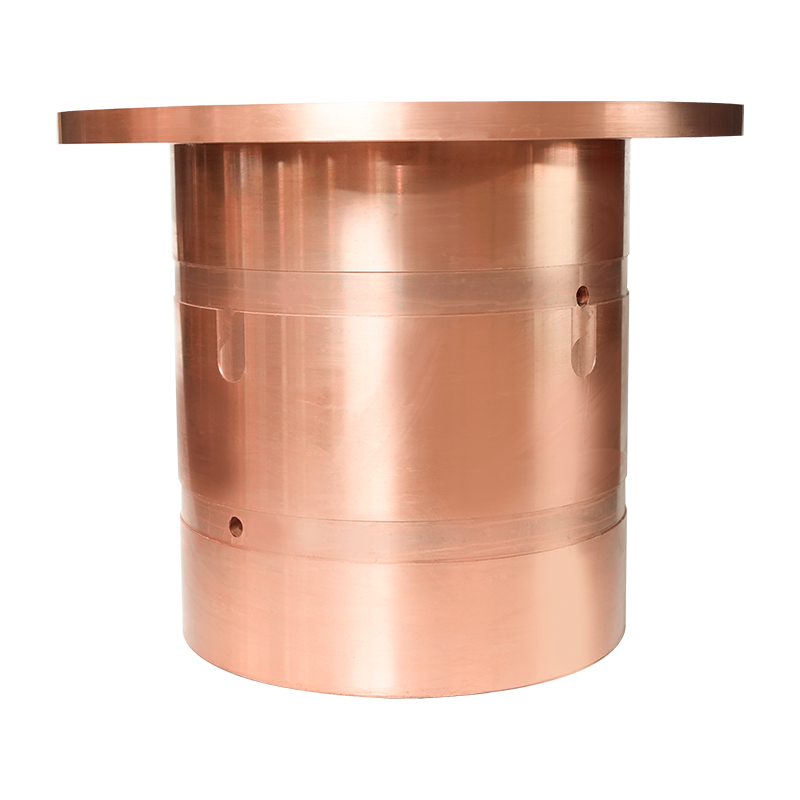
A worm gear shaft, typically made from hardened steel, performs best when paired with a copper worm gear, usually cast in bronze or brass alloy, rather than a same metal combination. This dissimilar metal pairing reduces friction, dissipates heat more effectively, and prevents galling between the two moving parts. For applications requiring high reduction ratios and quiet operation, a steel worm gear shaft matched with a copper worm gear remains the standard configuration across gearboxes, lifts, and precision machinery.
- Heavy LoadSteel shaft with tin bronze worm gear handles sustained torque well
- Precision MotionGround worm gear shaft with phosphor bronze gear reduces backlash
- Cost SensitiveBrass copper worm gear offers a balance of price and wear resistance
Understanding How a Worm Gear Shaft and Copper Worm Gear Work Together
A worm gear shaft is a helically threaded cylindrical rod that meshes with a toothed wheel known as the worm gear, converting rotational motion between perpendicular axes while achieving significant speed reduction in a compact space. Because the sliding contact between the shaft threads and the gear teeth generates continuous friction, material selection for both components directly determines system lifespan and efficiency.
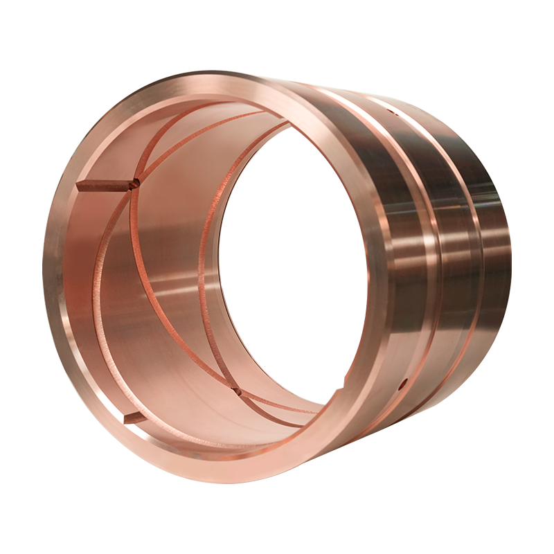
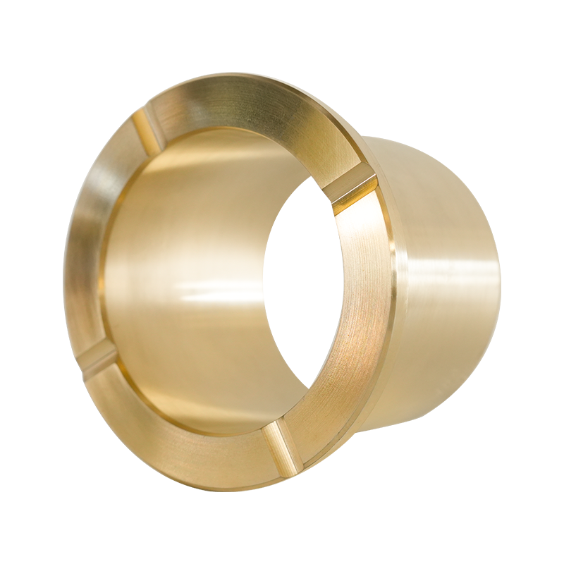
The copper worm gear plays a critical role in this pairing because copper alloys, particularly bronze, have naturally low friction coefficients against steel and possess self lubricating properties under boundary lubrication conditions. This is why the worm shaft is almost always hardened steel while the mating gear is copper based, rather than reversing the material assignment.
Why Dissimilar Metals Matter in Worm Drives
Using two hardened steel components together in a worm drive often leads to premature galling and seizure due to similar crystalline structures welding together under pressure. A copper worm gear avoids this failure mode entirely, since its softer, more ductile structure absorbs micro shock loads while the harder steel shaft resists deformation.
Comparing Copper Worm Gear Alloys for Different Applications
Not every copper worm gear uses the same alloy composition. The table below compares common bronze and brass options used alongside a worm gear shaft in industrial and precision applications.
Comparison of copper worm gear alloy types and typical performance characteristics
| Alloy Type |
Primary Composition |
Load Capacity |
Best Application |
| Tin Bronze |
Copper, Tin, Zinc |
High |
Heavy industrial gearboxes, elevators |
| Phosphor Bronze |
Copper, Tin, Phosphorus |
High |
Precision instruments, low backlash drives |
| Aluminum Bronze |
Copper, Aluminum, Iron |
Very High |
Marine equipment, corrosive environments |
| Manganese Bronze |
Copper, Zinc, Manganese |
Medium to High |
General industrial machinery |
| Brass |
Copper, Zinc |
Medium |
Light duty gear reducers, cost sensitive builds |
Tin bronze and phosphor bronze remain the most widely specified copper worm gear alloys because their tin content improves both wear resistance and load carrying capacity compared to standard brass, which is why they dominate applications where the worm gear shaft experiences continuous engagement.
Key Design Factors That Affect Worm Gear Shaft Performance
Beyond material choice, several engineering parameters influence how well a worm gear shaft and its mating copper worm gear perform together under real operating conditions.
1Lead Angle and Self Locking Behavior
The lead angle of the worm gear shaft determines whether the system is self locking, meaning the gear cannot back drive the shaft. Lead angles below 6 degrees typically produce self locking behavior, which is valuable in lifting equipment where holding a load without a brake is required.
2Center Distance and Reduction Ratio
Center distance between the worm gear shaft and the copper worm gear axis, combined with the number of gear teeth, determines the overall reduction ratio. Single start worm shafts commonly achieve ratios between 10 to 1 and 100 to 1 in a single gear stage, far exceeding what standard spur gears can offer in the same footprint.
3Surface Finish and Hardness
A worm gear shaft with a ground and polished thread surface, typically hardened to 58 to 62 HRC, significantly reduces wear on the softer copper worm gear teeth. Rougher shaft finishes accelerate gear tooth wear even when the correct bronze alloy is selected.
How to Select the Right Worm Gear Shaft and Copper Worm Gear Set
Matching a worm gear shaft to the correct copper worm gear requires evaluating several operating conditions before finalizing a design or purchase decision.
- Calculate the required torque output and expected duty cycle of the application
- Determine whether self locking behavior is needed for holding loads without power
- Select a copper worm gear alloy based on load, environment, and corrosion exposure
- Confirm shaft hardness and surface finish specifications match the intended service life
- Verify lubrication compatibility between the shaft material and the copper worm gear
Field data from industrial gear applications shows that properly lubricated bronze worm gear sets can achieve service lives exceeding 20000 operating hours, compared to significantly shorter lifespans when mismatched materials or inadequate lubrication are used.
Installation and Maintenance Practices for Worm Gear Drives
Proper installation and ongoing maintenance extend the working life of both the worm gear shaft and the copper worm gear, reducing unplanned downtime in production environments.
- Align Shaft and Gear PreciselyMisalignment concentrates load on a narrow contact band, accelerating gear wear
- Use Recommended Lubricant GradeApply extreme pressure gear oil formulated for bronze on steel contact
- Monitor Operating TemperatureSustained temperatures above 90 degrees Celsius often indicate insufficient lubrication
- Inspect Backlash PeriodicallyIncreasing backlash signals gradual wear on the copper worm gear teeth
- Break In New Gear Sets GraduallyRun new assemblies at reduced load before full duty operation
Manufacturing Methods Behind Reliable Copper Worm Gear Components
The manufacturing process used to produce a copper worm gear significantly affects its internal grain structure and long term durability when paired with a worm gear shaft.
Sand Casting
Sand casting remains a common method for producing copper worm gear blanks, offering flexibility for various sizes before final machining establishes precise tooth geometry and surface finish.
Centrifugal Casting
Centrifugal casting produces a denser, more uniform grain structure in the copper worm gear by using rotational force during solidification, which can improve mechanical properties compared to standard static casting methods.
Sourcing Quality Worm Gear Shaft and Copper Worm Gear Components
Selecting a supplier for worm gear shaft and copper worm gear components involves more than comparing price per unit. Consistent alloy composition, dimensional accuracy, and documented hardness testing all contribute to predictable performance once the gear set is installed in a working system.
Buyers should request material certification for the copper worm gear alloy along with dimensional inspection reports, since variations in tin content as small as one percent can measurably affect wear resistance over the operating life of the gear set.
A manufacturer offering a complete range of worm gear shaft and copper worm gear combinations, along with custom casting capabilities for specific alloy and size requirements, makes it easier for engineers to source matched, compatible components from a single reliable production source rather than combining parts from inconsistent suppliers.



 English
 日本語
日本語 русский
 Deutsch